Connecting a trailer to your tow vehicle requires more than just hitching it up; it demands a robust and reliable electrical connection. Misunderstandings about Standard 6-Pin Trailer Wiring Schematics & Color Codes can lead to more than just dim lights – they can compromise your safety with non-functional brake lights, disabled electric brakes, or even a vehicle fire from blown fuses and overloaded circuits. This guide will demystify trailer wiring, helping you connect confidently and safely.
At a Glance: Key Takeaways for Trailer Wiring Success
- Grounding is Paramount: The white wire is your most critical connection. A poor ground causes 90% of lighting issues.
- Know Your Connector: Different trailers use different connectors (4, 5, 6, 7-way) for varying functionalities. This guide focuses on the versatile 6-way.
- Color Codes are Your Compass: Industry-standard color codes are vital, but always double-check pin functions, especially with 6-way connectors, as some older standards might vary.
- Gauge Matters: Use appropriate wire gauges for each circuit to prevent voltage drop and ensure optimal performance, especially for brakes and auxiliary power.
- Protection is Prevention: Secure wiring, use protective sheathing, and weatherproof connectors to combat corrosion and damage.
Why Electrical Signals Are Your Trailer's Lifeline
Think of your trailer's wiring as its nervous system, transmitting vital signals from your tow vehicle to ensure safe operation. These signals control essential functions like:
- Road Visibility: Taillights, running lights, and side markers make your trailer visible to others, especially at night or in adverse weather.
- Intent to Turn or Stop: Brake lights and turn signals communicate your intentions to drivers behind you, preventing collisions.
- Auxiliary Power: For campers and horse trailers, a 12V power line can charge onboard batteries or power accessories.
- Braking Control: Electric trailer brakes are a game-changer for heavier loads, requiring a dedicated circuit to operate safely.
Ignoring proper wiring isn't just a minor inconvenience; it's a significant safety hazard. Let's ensure your trailer's nervous system is perfectly aligned with your vehicle's.
The Foundation: Understanding 4-Wire Basic Trailer Wiring
Before diving into the specifics of a 6-pin setup, it's crucial to understand the universal language of trailer wiring, which starts with the basic 4-wire system. This forms the bedrock for all more complex connectors. Most aftermarket and OEM harnesses adhere to these industry-standard colors:
- White: This is your Ground wire, essential for completing all electrical circuits. Without a proper ground, nothing works.
- Brown: Controls your Tail / Running Lights, which include side marker lights and license plate lights, illuminating the trailer for night driving.
- Yellow: Handles the Left Turn Signal & Stop light functions.
- Green: Manages the Right Turn Signal & Stop light functions.
A helpful mnemonic to remember these basic colors: Green for Right, Yellow for Left, White for Ground (or Earth), and Brown for the "bottom" lights (running lights). This foundational understanding makes it easier to tackle more complex systems.
A Quick Tour of Common Trailer Connector Types
Trailer connectors come in various shapes and sizes, each designed for specific levels of functionality. Understanding these helps put the 6-way into context:
- 4-Way Flat Connector: The simplest and most common for small utility or boat trailers. It covers basic lighting: ground, tail lights, left turn/brake, and right turn/brake.
- 5-Way Flat Connector: An upgrade from the 4-way, typically found on boat trailers with hydraulic surge brakes. It adds a blue wire for reverse lights or a reverse lockout solenoid, preventing brakes from engaging when backing up.
- 6-Way Round Connector: This is where we start adding significant power and control. Popular for horse trailers, some campers, and utility trailers requiring electric brakes or auxiliary power.
- 7-Way RV Blade Connector: The "gold standard" for heavy-duty RVs and large freight trailers. It provides the full suite of functions: ground, tail lights, left/right turn/brake, electric brakes, 12V auxiliary power, and reverse lights.
The Main Event: Deciphering Your Standard 6-Way Round Connector
The 6-way round connector is a workhorse, bridging the gap between basic lighting and more advanced trailer needs. It’s particularly common for trailers that require electric brakes or a dedicated 12V power line for charging or accessories. Because of its versatility, understanding its pinout and color codes is paramount for anyone towing a medium-sized trailer.
The key to a reliable 6-way connection lies in adhering to the standard pinout. It's crucial to note that while the colors are generally consistent, there have been some variations in older systems, particularly concerning the center pin's function. Always verify with a diagram or test light if unsure.
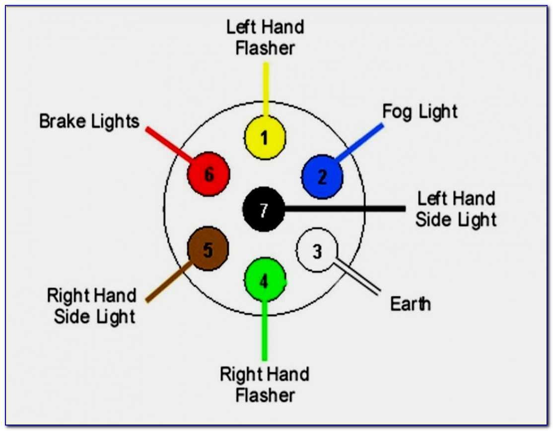
Here’s the breakdown of the typical standard 6-way round pinout and its corresponding color codes:
- Pin #1: Common Ground (White, Min 12 AWG)
- Function: This is the lifeline for all circuits. A solid, clean ground connection is non-negotiable for consistent performance.
- Why it's important: Without a good ground, electricity can't complete its circuit, leading to dim, flickering, or non-functional lights and brakes.
- Pin #2: Electric Trailer Brakes (Blue, Min 12 AWG)
- Function: This wire carries the modulated power signal from your vehicle's brake controller to the trailer's electric brake magnets.
- Why it's important: Crucial for safety, especially with heavier trailers. It allows your vehicle to apply the trailer's brakes proportionally when you slow down or stop.
- Pin #3: Tail/Running/License Plate (Brown, Min 16 AWG)
- Function: Powers all rearward-facing running lights, side marker lights, and the license plate illumination.
- Why it's important: Ensures your trailer is visible from the rear and sides during nighttime towing, fulfilling legal requirements.
- Pin #4: 12V+ Auxiliary Charging Circuit (Black/Red, Min 12 AWG)
- Function: Provides a constant 12-volt power feed from your tow vehicle to the trailer. This can charge trailer batteries, power interior lights, or run other 12V accessories like a breakaway switch.
- Why it's important: Essential for campers, horse trailers, or any trailer with onboard electrical systems, ensuring power when disconnected from the tow vehicle or for charging while driving.
- Pin #5: Left Turn/Brake (Yellow, Min 16 AWG)
- Function: Controls the left turn signal and the left brake light.
- Why it's important: Communicates your turning and stopping intentions to other drivers.
- Pin #6: Right Turn/Brake (Green, Min 16 AWG)
- Function: Controls the right turn signal and the right brake light.
- Why it's important: As with the left, this is critical for road safety and compliance.
Important Note on 6-Way Standards
While the pinout above is widely accepted, historical variations exist. Specifically, older 6-way connectors might have used the center pin for auxiliary power, while the brake wire was elsewhere. Always consult your trailer's manual or a wiring diagram specific to your connector if you're working with an older or unfamiliar setup. When dealing with any 6 pin trailer wiring, a test light or multimeter is your best friend to confirm wire functions before making permanent connections.
Comprehensive Color Code Reference Summary
To make your wiring journey even smoother, here's a consolidated table of standard color codes across various connector types. This quick reference can save you time and prevent misconnections.
| Wire Color | Function | Common Connector Types | Min. AWG (Typical) |
|---|---|---|---|
| White | Ground | All Types | 18 AWG (4-way) / 12 AWG (6, 7-way) |
| Brown | Tail / Running Lights | All Types | 18 AWG (4-way) / 16 AWG (6, 7-way) |
| Yellow | Left Turn / Brake Lights | All Types | 18 AWG (4-way) / 16 AWG (6, 7-way) |
| Green | Right Turn / Brake Lights | All Types | 18 AWG (4-way) / 16 AWG (6, 7-way) |
| Blue | Electric Brake Controller Output / Hydraulic Lockout | 5, 6, 7-Way | 12 AWG |
| Black or Red | 12V Battery Feed (Auxiliary Power) | 6, 7-Way | 12 AWG |
| Purple/Orange | Reverse Lights | 5, 7-Way | 16 AWG |
Installation Best Practices: Build to Last
A wiring job is only as good as its weakest link. Following these best practices will ensure your trailer wiring is reliable, durable, and safe for years to come.
1. Grounding is Key: The Unsung Hero
Over 90% of trailer lighting failures can be traced back to a poor ground connection. The white ground wire is not merely an afterthought; it's the foundation of your electrical system.
- Direct Connection: Always connect the white ground wire directly to a clean, bare metal surface on the trailer frame.
- Prepare the Surface: Before attaching, scrape off any paint, rust, or primer from the contact point. Use a wire brush if necessary.
- Secure Connection: Utilize a ring terminal, and secure it firmly with a self-tapping screw or bolt. A star washer between the terminal and the frame dramatically improves electrical contact by biting into the metal.
- Avoid the Hitch Ball: Never rely on the hitch ball itself for grounding. Grease, rust, and movement make it an unreliable, intermittent connection at best.
2. Select the Correct Wire Gauge: Powering Your Purpose
Using the right wire gauge is not just a recommendation; it's an engineering necessity. Too thin a wire for the current it carries can lead to problems.
- Signal Lights (Tail, Turn, Brake): For these circuits, 16-14 AWG (American Wire Gauge) wire is typically sufficient. They draw relatively low current.
- Heavy-Duty Circuits (Ground, Power, Electric Brakes): These circuits handle significantly more current. You must use thicker 12-10 AWG wire.
- Why it matters: Thicker wire has less resistance, meaning less voltage drop. If your ground, power, or brake wires are too thin, you'll experience dim lights, weak electric brakes, or even wire overheating.
3. Routing & Securing: Out of Harm's Way
Proper routing protects your wiring from the elements and physical damage.
- Slack Loop: At the trailer connector end, leave a generous "slack loop." This extra length prevents wires from pulling taut and stressing connections during tight turns or when the trailer articulates.
- Protection: Wrap all wires in corrugated plastic tubing or flexible wire loom. This shields them from abrasion, heat, and road debris.
- Secure Firmly: Secure the wrapped harness along the inside of the trailer frame using zip ties, wire clamps, or specialized clips. Ensure it's away from moving parts (like axles or suspension components) and hot surfaces (like exhaust pipes).
4. Connector Protection: Guard Against the Elements
Your trailer connector is exposed to some of the harshest conditions. Protecting it extends its lifespan and ensures reliable connections.
- Dust/Waterproof Cap: When not in use, always cover the connector with a dust/waterproof cap. This keeps out moisture, dirt, and road grime.
- Dielectric Grease: Periodically apply dielectric grease to the connector terminals. This non-conductive grease repels water, prevents corrosion, and facilitates easy connection and disconnection without interfering with electrical conductivity.
Troubleshooting: When Things Go Dim or Stop Moving
Even with the best installation, issues can arise. Knowing how to systematically troubleshoot your trailer's electrical system will save you time, money, and frustration.
Trailer Light Troubleshooting (The Most Common Issues)
- Start with the Connection:
- First, disconnect, inspect, and thoroughly clean both the truck and trailer connectors. Look for bent pins, dirt, or corrosion.
- Apply a generous spray of WD-40 or dielectric lubricant, then reconnect, ensuring full, firm insertion.
- Single Light Out?
- If only one light isn't working, the simplest solution is often a faulty bulb or a corroded light assembly. Replace the bulb, or if needed, the entire light unit.
- No Lights (or All Lights Dim)?
- The Ground Check: This is the prime suspect. Use a jumper wire to connect the trailer's frame directly to the negative terminal of your vehicle's battery. If the lights suddenly spring to life, your original ground connection on the trailer is faulty. Inspect the white ground wire connection to the frame – clean, tighten, or re-establish it.
- Vehicle Ground: Alternatively, use a digital multimeter to check continuity between the truck's ground pin (white wire location) and the truck's chassis.
- Is the Problem on the Truck or Trailer?
- Disconnect the trailer. Have a helper activate the problematic lights (e.g., press the brake pedal, turn on the hazards).
- Using a multimeter or a 12V test light, probe the corresponding pin on the truck-side connector.
- If 12V+ is present: The problem lies within the trailer's wiring. Move to the next step.
- If no power: The issue is with the vehicle. Check your vehicle's fuse box for blown fuses related to trailer lighting. Also, inspect the wiring harness along the vehicle's frame for any chafed, cut, or corroded wires.
- Troubleshooting Trailer Wiring:
- Methodically inspect the entire length of the trailer's wiring harness. Look for visible signs of damage: chafed insulation, exposed copper, cuts, or loose electrical connectors (especially where wires split off to individual lights).
- Repair any damaged sections using heat-shrink butt connectors (never just electrical tape) or by replacing the entire section if damage is extensive.
Electric Trailer Brake Troubleshooting (For 6-Way and 7-Way Systems)
- Connection Cleanliness: Just like with lights, ensure the truck and trailer connectors are clean and fully inserted. Use dielectric lubricant.
- Verify Brake Controller Function:
- Confirm your trailer brake controller in the vehicle powers on.
- With a multimeter, probe the electric brake control pin (usually the blue wire location) on the truck-side connector.
- Have a second person press the brake pedal. You should see the voltage rise from 0V as the pedal is depressed (often indicating brake gain). If you get 0V even with the pedal pressed, the issue is likely with the brake controller itself or its wiring to the truck connector.
- Check Trailer Brake Wiring:
- Trace the blue wire from the trailer connector back to the brake magnets inside the drums.
- Each brake magnet typically has two wires: one connecting to the brake control circuit (blue wire feed) and the other to the trailer's ground.
- Inspect for loose splices, cut wires, or chafed insulation from the brake drums all the way to the trailer connector.
- With the brake pedal depressed (and your multimeter connected to the blue wire feed and trailer ground), probe the wires going to each brake magnet. You should see voltage. If not, the break in the circuit is in the trailer wiring.
- Check Brake Magnets:
- If power is reaching the brake magnets but the brakes aren't engaging, the magnets themselves might be faulty or worn.
- This requires removing the brake drum to visually inspect the magnets. They should have a smooth, even surface. Replace if they appear worn down, scarred, or if resistance tests (using an ohmmeter) show an open circuit.
Common Mistakes to Avoid: Learn From Others' Errors
Steering clear of these common pitfalls will save you a lot of grief and expense.
- Relying on the hitch ball for grounding: As mentioned, this is a recipe for intermittent lighting and electrical headaches. Always use a dedicated, clean frame ground.
- Using "Scotch Lock" or "Vampire" connectors: While convenient, these connectors are notorious for failing. They pierce wire insulation, leaving the copper exposed to moisture and corrosion, leading to intermittent connections. Always opt for proper crimp-on heat-shrink butt connectors, which seal against the elements.
- Mixing up 6-Way round plug definitions: Due to historical variations, mistakenly connecting your 12V auxiliary power line to the electric brake line (or vice-versa) can have serious consequences. If 12V constant power hits your brake magnets, they'll lock up your trailer brakes, potentially causing dangerous skids or even a fire. Always double-check your 6 pin trailer wiring schematic and test your connections before hitting the road.
- Leaving excessive bare wire exposed: When stripping wires, expose only enough copper to make a secure connection within the terminal. Too much exposed wire increases the risk of short circuits.
- Neglecting strain relief: Wires pulling tight at connections will eventually break. Always provide adequate slack and secure the wiring harness to prevent tension on individual connections.
Final Checks for Confident Towing
Once your wiring is complete, perform a thorough walk-around test. With your vehicle running and connected to the trailer:
- Running Lights: Turn on your vehicle's headlights. All trailer running lights, side markers, and license plate lights should illuminate.
- Left Turn Signal: Activate your left turn signal. The trailer's left turn signal should flash in sync.
- Right Turn Signal: Activate your right turn signal. The trailer's right turn signal should flash in sync.
- Brake Lights: Have a helper press the brake pedal. Both the left and right brake lights on the trailer should light up brightly.
- Auxiliary Power (6-Way & 7-Way): If your trailer has a battery or 12V accessories, confirm they are receiving power (e.g., check battery voltage or interior lights).
- Electric Brakes (6-Way & 7-Way): Test your trailer brakes using your brake controller's manual override. You should feel the trailer's brakes engage, and the vehicle's braking should be noticeable. Do this safely at a low speed in a clear area.
By understanding the schematics, respecting color codes, and diligently following best practices, you empower yourself to tackle trailer wiring with confidence. A well-wired trailer isn't just a convenience; it's a commitment to safety for yourself and everyone else on the road. Drive safe!